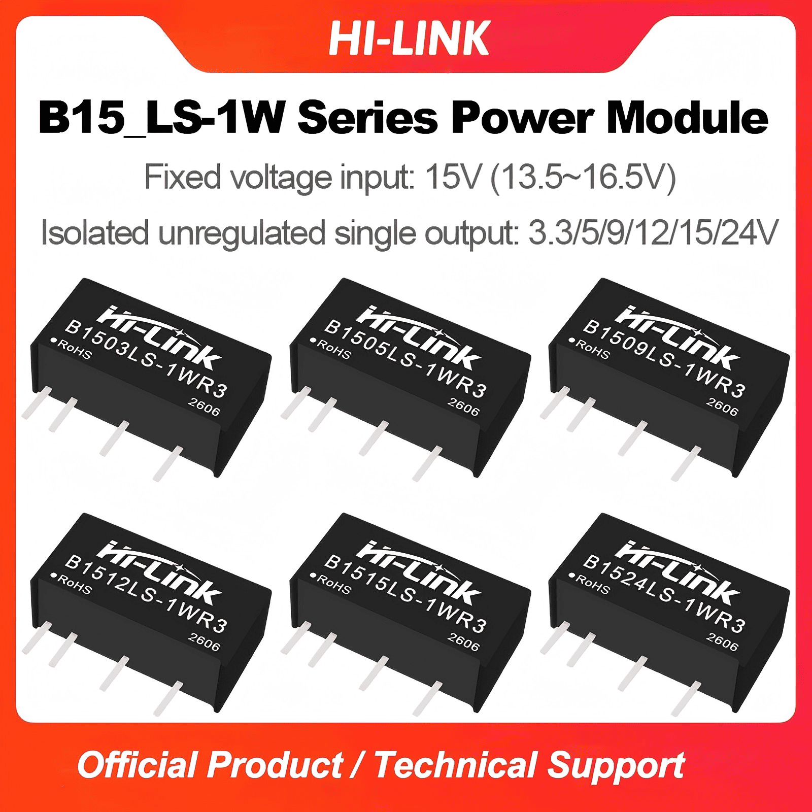
B1505LS/B1512LS/B1503LS/B1509LS/B1515LS/B1524LS-1WR3 DC to DC 1W step down power converter module
-
Visitor6
-
Buycount:
-
Price$0.62
Product Feature
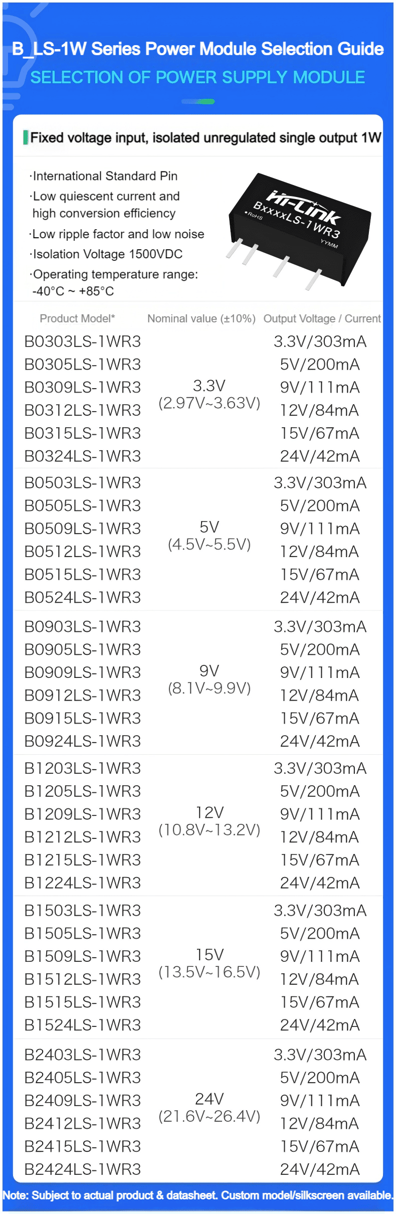
1. Fixed voltage input, isolated and regulated output, power 1W
2. isolation voltage≤1500VDC
3. Low static current and high conversion efficiency
4. Low ripple, low noise
5. output short-circuit protection :Sustainable short circuit protection, automatic recovery
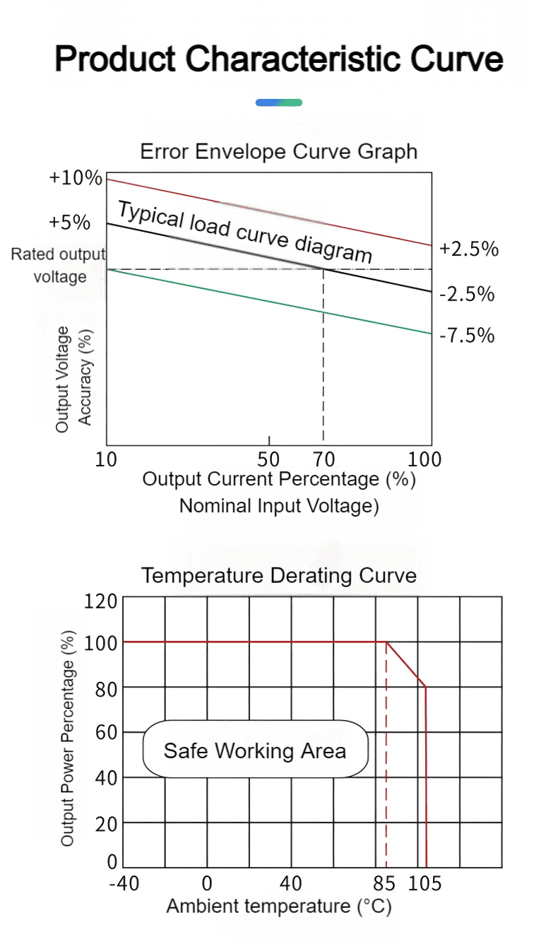
6. operating temperature range :-40°C~+85°C
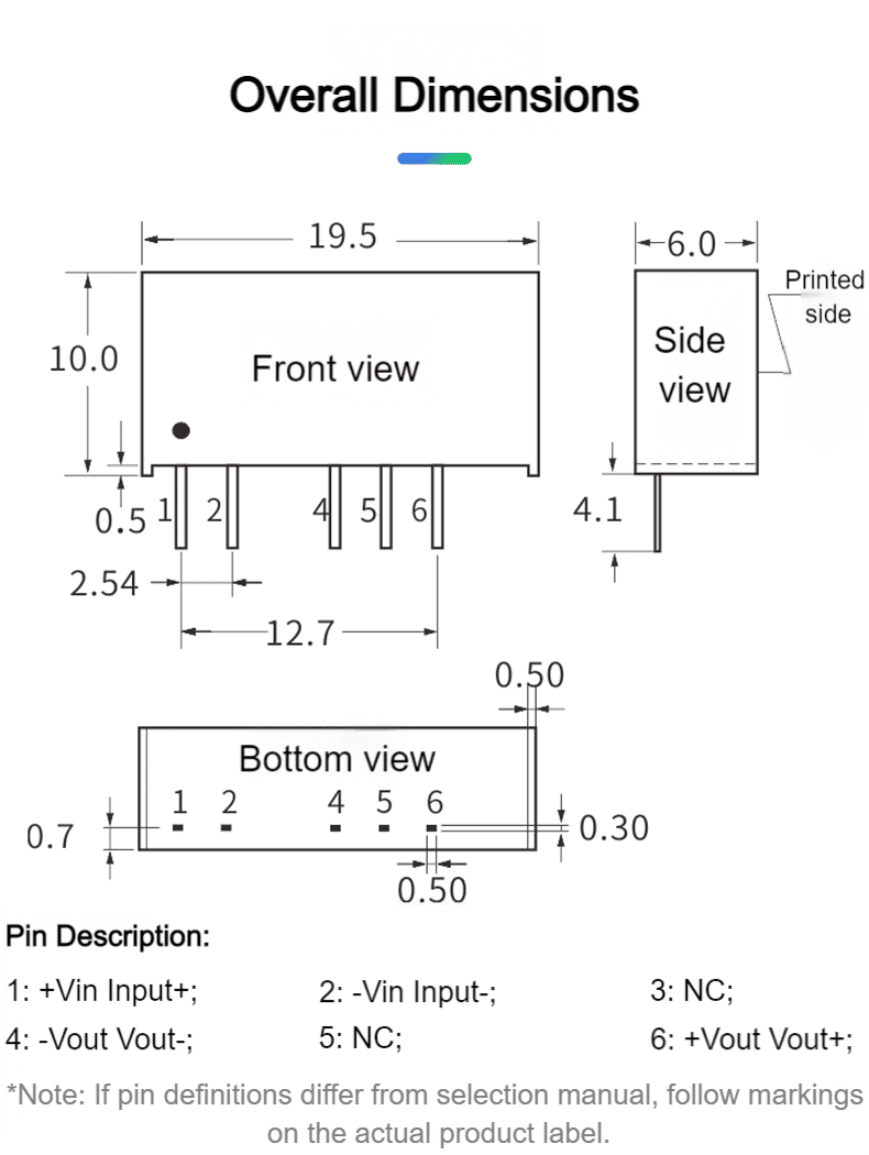
7. Small SIP package,plastic shell
8. High reliability and long life design,continuous working time MTBF≥3.5 million hours (3500000Hrs)
Enviroment Condition
| Project name | Qualification | Unit | Notes |
| Working enviroment temperature | -40—+85 | ℃ | |
| Storage temperture | -40—+80 ℃ | ℃ | |
| Relative humidity | 5—95 | % | |
| Heat dissipation mode | natural cooling | ||
| Atmospheric pressure | 80—106 Kpa | Kpa | |
| Vibrate | Vibration coefficient 10~500Hz,2G10min./1cycle, 60min.each along X,Y,Z axes | Meet the requirements of secondary road transportation |
Input Characteristics
| Items | Working conditions | Min. | Typ. | Max. | Unit |
Input current (fully loaded/ unloaded) | 3.3VDC Input | -- | 378/6 | --/12 | mA |
| 5VDC Input | -- | 224/5 | --/10 | ||
| 12VDC Input | -- | 93/3 | --/5 | ||
| 15VDC Input | -- | 74/2 | --/4 | ||
| 24VDC Input | -- | 47/1 | --/2 | ||
| Reflected Ripple Current | 4.5 | -- | 15 | -- | mA |
| Impulse voltage (Isec.max) | 3.3VDC Input | -0.7 | -- | 5 | VDC |
| 5VDC Input | -0.7 | -- | 9 | ||
| 12VDC Input | -0.7 | -- | 18 | ||
| 15VDC Input | -0.7 | -- | 21 | ||
| 24VDC Input | -0.7 | -- | 30 | ||
| Input filter type | Capacitive filtering | ||||
| Hot plug | Not available | ||||
Output Characteristics(15v/±34mA)
| Items | Working and test conditions | Min. | Typ. | Max. | Unit | |
| Output load | Load percentage | 10 | -- | 100 | % | |
| Output VoltageAccuracy | Refer to Error Envelope Curve | -- | -- | ±15.0 | % | |
| Linear adjustment rate | Input voltage variation ±1% | 3.3V Output | -- | -- | ±1.5 | % |
| Others | -- | -- | ±1.2 | % | ||
| Load Regulation | 10%~100% Load | 3.3VDC Output | -- | 18 | 12 | % |
| 5VDC Output | -- | 12 | % | |||
| 9VDC Output | -- | 8 | % | |||
| 12VDC Output | -- | 7 | % | |||
| 15VDC Output | -- | 6 | % | |||
| 24VDC Output | -- | 5 | % | |||
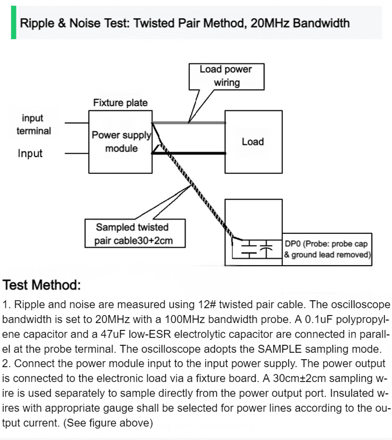
| Ripple & Noise | Pure resistive load, 20MHz bandwidth, peak-to-peak | -- | 30 | 80 | mVp-p | |
| Temperature Drift Coefficient | Full load | -- | -- | ±0.03 | %/°C | |
| Output short circuit protection | Continuous short circuit protection, automatic recovery | |||||
| Note: ①The test method of ripple and noise is twisted pair test method. | ||||||
Typical Application Circuits
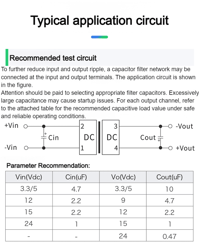
1. General application:
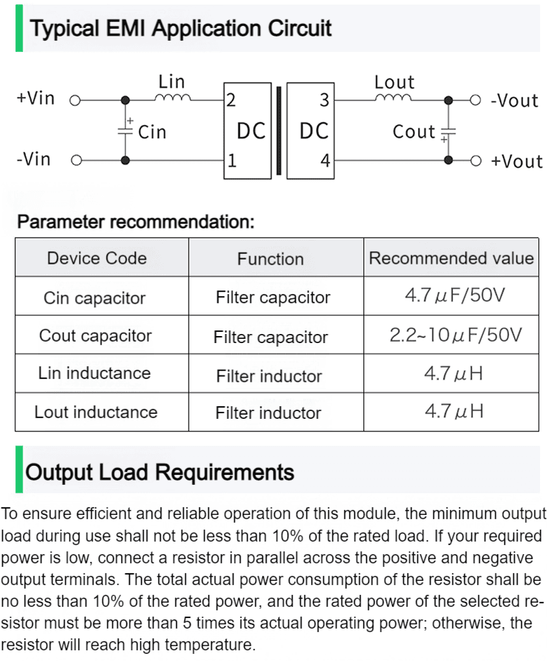
If it is required to further reduce the input and output ripple, a capacitor filter network can be connected to the input and output
ends, and the application circuit is shown in Figure 1.
However, attention should be paid to the selection of appropriate filter capacitors. If the capacitor is too large, it is likely to
cause startup problems. For each output, under the condition of ensuring safe and reliable operation, the recommended
capacitive load value is shown in Table 1