
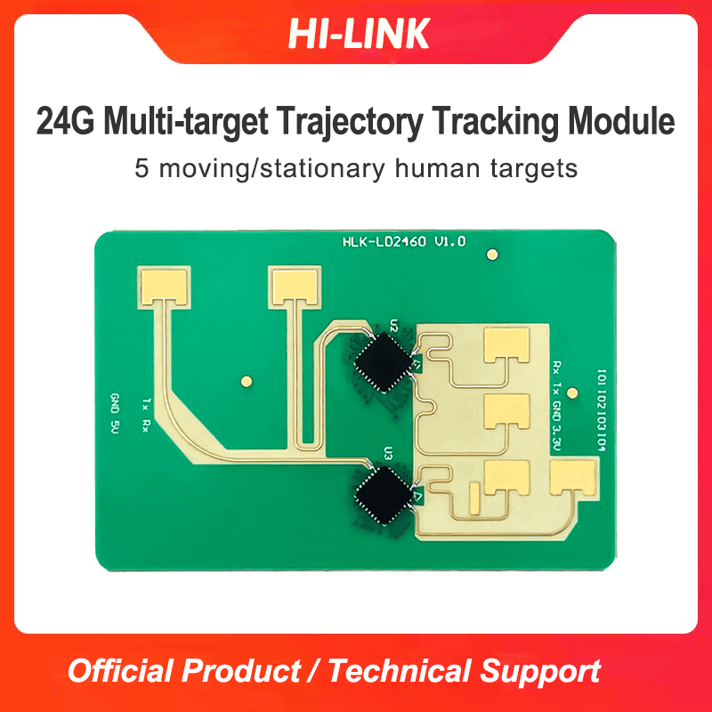
HLK-LD2460 2T4R 24G Millimeter Wave High-precision Multiple Targets Human Perception Trajectory Tracking Radar Sensor Module
-
Visitor19657
-
Buycount:
-
Price$12.89


Download Files:
HLK-LD2401:
https://drive.google.com/drive/folders/1lzr9p_PwXhF-kYRUyi09oY0CzpZk_lf3?usp=sharing
HLK-LD2402:
https://drive.google.com/file/d/1SmigbSjFt1toA7W5wEuI2Qy-1CSR6PQn/view?usp=sharing
HLK-LD2410C: https://drive.google.com/drive/folders/1ypOlacBmmFXY6lDQ0f1hEJFmczNe-0WG
HLK-LD2410B: https://drive.google.com/drive/folders/16zI-fium_BZeP08EyQke0rWp0BJTMvw3
HLK-LD2410: https://drive.google.com/drive/folders/1lCQv3mfHJ3XKXzweeHPFnJ_8_D_EWEKk
HLK-LD2410S: https://drive.google.com/drive/folders/1wC8KC-DaNavNbpeVouZ1HdiBzZ9YrAcg
HLK-LD2410D: https://drive.google.com/drive/folders/1inGVZojrH6ZmOwg66IucZ3wGe7JzQpX1?usp=sharing
HLK-LD2420: https://drive.google.com/drive/folders/1IggDH6ejNSOs8EklQbAXcqUI7KENSZLt?usp=sharing
HLK-LD2411: https://drive.google.com/drive/folders/1ZAFkDPr_BLQpmw1h6furMvg-hcByOt5z
HLK-LD2412: https://drive.google.com/drive/folders/17TAVgH5YI_6naA24dpjnJjm2v28alRPl?usp=sharing
HLK-LD2413:
https://drive.google.com/file/d/1SmigbSjFt1toA7W5wEuI2Qy-1CSR6PQn/view?usp=sharing
HLK-LD2451: https://drive.google.com/drive/folders/1Xl7lnvCAQHD2xjOfU_lpxdr0GGXO0-F6?usp=sharing
HLK-LD2460: https://drive.google.com/drive/folders/1JkImVaRfSgP8taq5W4aW_bCxlcqeHVan?usp=sharing
HLK-LD2461: https://drive.google.com/drive/folders/14_KgZpL4Th2LTRuq_W0X_ePjHu_Z6lcS
HLK-LD2450: https://drive.google.com/drive/folders/1kTt0Z3hjKKrIF3OCIDGdwQ4KotDJ8SGA
HLK-LD2415H: https://drive.google.com/drive/folders/1eOj3xdVOvwmmCniIhfUZZwE_R63wWeKO
Product Description
HLK-LD2460 is a 24GHz millimeter wave radar product for human perception, with distance angle test function. It consists of 1-transmitter and 2-receiver millimeter wave radar chips, high-performance microstrip antenna, high-performance MCU, high-performance Bluetooth SOC and peripheral auxiliary circuits. It uses FMCW waveform to accurately identify 3-5 human targets and estimate the location of the targets. This product can be used in scenes such as home, office, hotel, etc. to achieve accurate sensing of multiple moving, micro-moving or stationary human bodies.
Product parameters
(1) Detection angle and distance
| No. | Project | Function description | Index |
| 1 | Number of people detected | Number of people can be detected with the module | If a person is sitting or standing in the radar field of view, at least 3 people can be detected; if a person is moving, up to 5 people can be detected |
| 2 | Detection distance | The detection distance and conditions of the module in the bare board state | 1 Dynamic human body: within ±50°, distance ≥6m; ±50°~±60°, distance ≥5.5m 2 Static human body: within ±50°, distance ≥5m; ±50°~±60°, distance ≥4.5m |
| 3 | Distance resolution | The minimum distance distinguished by this module | 0.75m |
| 4 | Distance accuracy | The absolute error of the module in distance | ≤0.3m |
| 5 | Horizontal detection angle | The maximum horizontal angle that the module can detect | 120° |
| 6 | Vertical detection angle | The maximum vertical angle that the module can detect | 90° |
| 7 | Angular resolution | The minimum angle distinguished by this module | 40° |
| 8 | Angle accuracy | The module's absolute angle error | ≤5° |
| 9 | OTA function | Online upgrade function | Support |
| 10 | Motion trigger time | Refers to the detection time when a person is exercising | 0.5s |
| 11 | existence perception time | Refers to the detection time when a person is stationary | ≤30s |
(2) Electric performance
| No. | Project | Index |
| 1 | Working frequency band | 24GHz-24.25GHz |
| 2 | Working bandwidth | 250Mhz |
| 3 | EIRP | 13dBm |
| 4 | Modulation method | FMCW (Frequency Modulated Continuous Wave) |
| 5 | Working voltage | 5V |
| 6 | Working Current | ≤250mA |
| 7 | Working temperature | -40℃~85℃ |
| 8 | Storage temperature | -40℃~85℃ |
Module size and pin description


Module pin definition
| Pin No. | Name | IO type | Function | Illustration |
| 1 | 5V | PWR | Power input | DC5V |
| 2 | GND | GND | GND | GND |
| 3 | Tx1 | O | UART1 output | - |
| 4 | Rx1 | I | UART1 input | - |
| 5 | VDD33 | PWR | Power input | 3.3V/NC, not connected when not debugging |
| 6 | GND | GND | GND | GND |
| 7 | Tx2 | O | UART2 output | Radar data reporting and command response |
| 8 | Rx2 | I | UART2 input | Command receiving |
| 9 | IO1 | I/O | GPIO1/Reserved | - |
| 10 | IO2 | I/O | GPIO2/Reserved | - |
| 11 | IO3 | I/O | GPIO3/Reserved | - |
| 12 | IO4 | I/O | GPIO4/Reserved | - |
Table 1 Definition of radar pin
Warmly note: In order to receive serial port data normally, the serial port needs to share the same ground with the module.
Using connection figure

Figure 4 Schematic diagram of radar module and peripheral connection

