
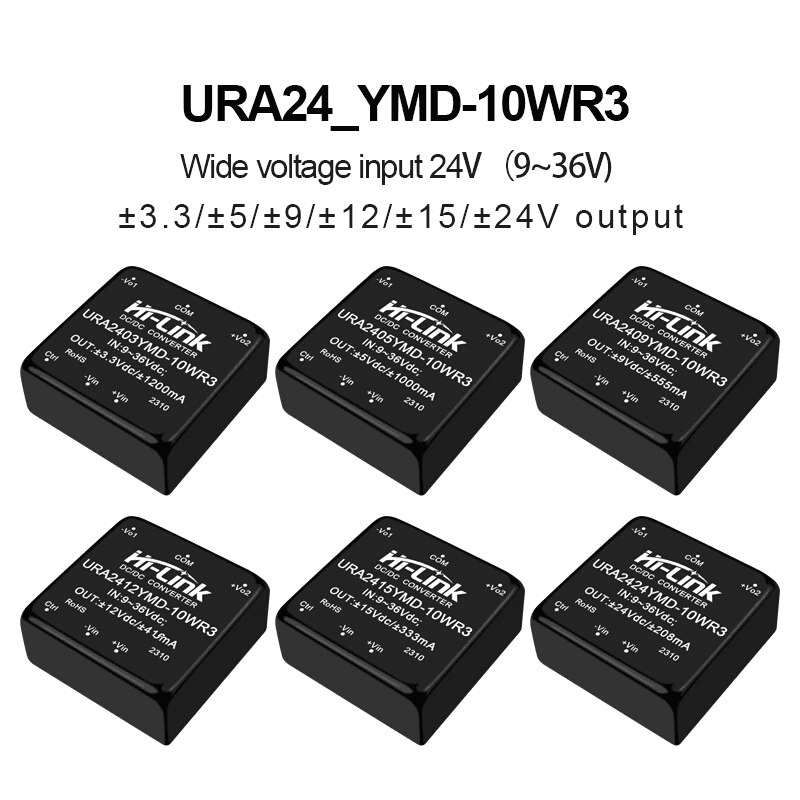
URA2405YMD-10WR3 URA2412/URA2424YMD DCDC isolated power module 110V to 3.3/9/12/15/24 dual output power converter
-
Visitor7904
-
Buycount:
-
Price$4.55

Download files:
DC to DC power module:
1W: https://drive.google.com/drive/folders/1vk6luTBKSC5gfwLJC-DbyEZYVDwk87JV
2W: https://drive.google.com/drive/folders/1vjf-77LCVQl16Hcb1phADiU3Hz14mhYB
3W: https://drive.google.com/drive/folders/13pTx02uL4moskJ-PQsBYFytdq2pPt2mN
5W: https://drive.google.com/drive/folders/1okF0YdP1Xs35HxnAkTm45WOK0kH7qlb5?
6W: https://drive.google.com/drive/folders/18IOw7PyIx99lbm3u0FEhkepC82w601sw
10W: https://drive.google.com/drive/folders/1vuJp5ZoJA9Ci0M4wCS8nT689LVzgh2tC
12W: https://drive.google.com/drive/folders/1becUdxQODQ25_A_iarNnun3Vmi_wow1g
20W: https://drive.google.com/drive/folders/182aHyvoN8J0fCurg65jOkfQp17dyaXP6
30W: https://drive.google.com/drive/folders/1StP-0SJDyFpH3yQMLLQjkQXMDXc-RGeP
40W: https://drive.google.com/drive/folders/1IXRm7dueYYTNoyXCFp88wRQexmKAgCLm
B0505S-1WR2: https://drive.google.com/file/d/16BPrOWkzOz7efnf3OvF1XjClKGnO6znv/view
AC to DC power module:
40W: https://drive.google.com/drive/folders/1jI-hITgxjtByhSCpUMmrJATHO8b_gpN7
30W(C): https://drive.google.com/drive/folders/1Nz-_SdQAuVha0JM7nJTelIfophZsmUYb
20W: https://drive.google.com/drive/folders/1PlLOzt_k3Ky5THYGOWP72jqxWSkJsU6Z
15W(C): https://drive.google.com/drive/folders/1vnVfcgQH-OvujpO6asvQvjIgmwUS2Pti
10W: https://drive.google.com/drive/folders/1zaMfq4Dm3brmRWhTGp9-49c8hN5HsIuk
5W: https://drive.google.com/drive/folders/1_dzDfHi9HOnj_b0RJHCGZ9j87ma8PU7g
3W: https://drive.google.com/drive/folders/1xz8MPw9KeQXDlyAQoI3KXzjCoL4yBRVP
2W: https://drive.google.com/file/d/1_UaUPWX9K5Bfavle4C1imVY0-WjY4yso/view
Product Feature
1. Wide input voltage range 4:1, isolated regulated output 10W
2. Isolation voltage 1500VDC
3. Transfer efficiency up to 91%
4. Ultra-long standby power consumption 0.036W(Typle)
5. Quick Start:1mS(Typ)
6. Operating temperature range :-40°C~+85°C
7. Metal case, low output ripple
8. International standard pin,direct installation of PCB board
9. Output short-circuit protection: continuous short circuit protection, automatic recovery
Enviroment Condition
| Project name | Qualification | Unit | Notes |
| Working enviroment temperature | -40—+85 | ℃ | |
| Storage temperture | -40—+125 ℃ | ℃ | |
| Relative humidity | 5—95 | % | |
| Heat dissipation mode | natural cooling | ||
| Atmospheric pressure | 80—106 Kpa | Kpa | |
| Ripple & Noise | 50/80(max) | Mvp-p |
Input Characteristics
| Item | Working conditions | Min. | Typ. | Max. | Unit | |
| Input currency( full loaded/ Unloaded | 24VDC Input Series | 3.3V | - | 402/1 | 413/2 | mA |
| others | - | 490/1 | 502/2 | |||
| 48VDC Input Series | 3.3V | - | 201/0.5 | 207/1 | ||
| others | - | 245/0.5 | 251/1 | |||
| 110VDC Input Series | 3.3V | - | 87/0.3 | 90/0.5 | ||
| others | - | 100/0.3 | 109/0.5 | |||
| Reflected ripple current | 24VDC Input Series | -- | 40 | -- | ||
| 48VDC Input Series | -- | 30 | -- | |||
| 110VDC Input Series | -- | 20 | -- | |||
Impulse voltage (Isec.max) | 24VDC Input Series | -0.7 | -- | 50 | ||
| 48VDC Input Series | -0.7 | -- | 100 | |||
| 110VDC Input Series | -0.7 | -- | 200 | |||
| Start voltage | 24VDC nominal input series, nominal input voltage | - | - | 9 | ||
| 48VDC nominal input series, nominal input voltage | - | - | 18 | |||
| 110VDC nominal input series, nominal input voltage | - | - | 40 | |||
| Input undervoltage protection | 24VDC nominal input series, nominal input voltage | 5.5 | 6.5 | - | ||
| 48VDC nominal input series, nominal input voltage | 12 | 15.5 | - | |||
| 110VDC nominal input series, nominal input voltage | 32 | 36 | - | |||
| Input filter type | Capacitance filter type | |||||
| Hot plugged | Non-support | |||||
Output Characteristics
| Project name | Working and testing condition | +V01 | -V02 | |||||
| Min. | Typ. | Max. | Min. | Typ. | Max. | |||
| output load | load percentage | 0% | - | 100% | 0% | - | 100% | |
| Output Voltage Accuracy | - | ±1.0% | ±2.0% | - | ±2.0% | ±3.0% | ||
| Linear adjustment rate | input voltage range | - | ±2.0% | ±0.5% | - | ±1.5% | ±2.0% | |
| Load adjustment rate | 20%~100% rate load, balanced | -- | ±0.5% | ±1.0% | - | ±4.0% | ±5.0% | |
| Ripple & Noise | Pure resistive load, 20HMz bandwidth, peak-to-peak | -- | 50mVp-p | 80mVp-p | - | 50mVp-p | 80mVp-p | |
| Output voltage regulation | Input voltage range | - | No adjustment end | - | - | No adjustment endNo adjustment end | - | |
| Output short circuit protection | Continuous short circuit protection, automatic recovery | |||||||
| Notes: Ripple and Noise Test Methods Twisted Pair Test Method | ||||||||
Note:
1、The above is only a list of typical products. If you need products beyond the list, please contact our sales. 2、The maximum capacitive load indicates the maximum capacitive load that + VO or - vo can be connected to,If the value is exceeded, the product will not start normally..
Typical Application Circuits

EMC parameter recommendation
| Component No. | Function | Recommended value |
| FMSE | Slow blowing fuse, selected according to the actual input current of the customer | |
| CY1 safety capacitor | 1nF/250Vac | |
Notes:More details please feel free to contact hi-link team.

