
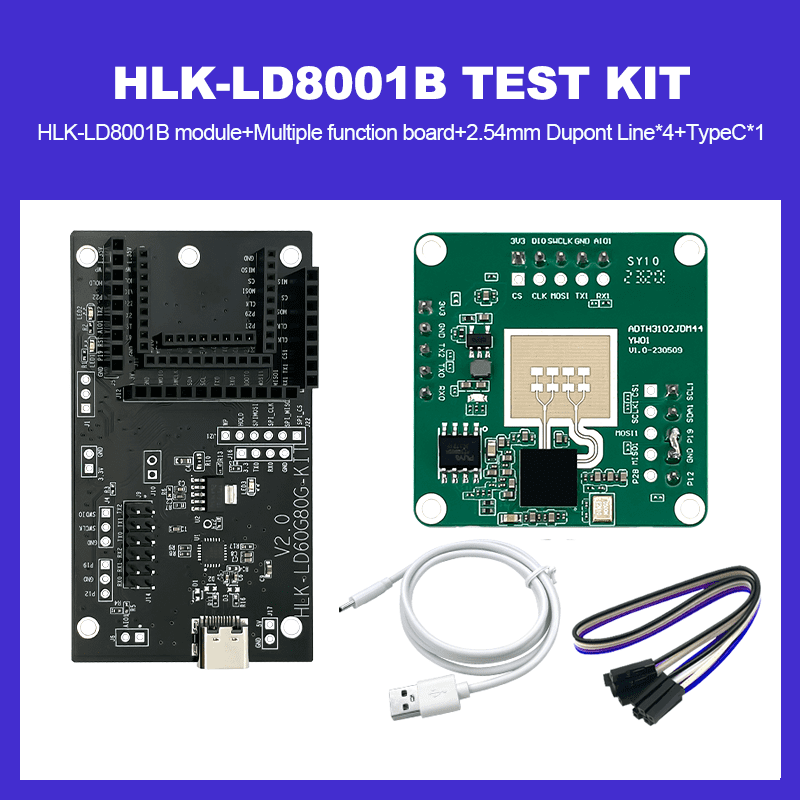
79G millimeter wave liquid level detection sensor HLK-LD8001B test kit/ development board non-contact radar module for high-precision level measurement
-
Visitor1694
-
Buycount:
-
Price$39.98

Radar Sensor module docs link:
https://drive.google.com/drive/folders/16h1POBPM-CN3x7FaBTZa6IErEnPA2w4d?usp=sharing
Product introduction
HLK-LD8001B is a radar induction module developed based on ADT3102 chip, with a single-chip integrated 76-81GHz RF transceiver system, 1T1R PCB high gain antenna, 1MB flash, radar signal processing unit, ARM ® Cortex ®- M3 kernel. This module is based on FMCW signal processing mechanism, combined with radar signal processing algorithm, to achieve high-precision ranging, suitable for high-precision liquid level and material level measurement.
Product characteristics
Radar detection based on FMCW frequency modulated continuous wave signal
The measurement distance can reach up to 15m
High precision continuous measurement with an error of+/-5mm
Antenna -3dB beam angle horizontal 100 °, elevation 80 °
Support SPI, Uart, and I2C standard communication interfaces
Small size, 35.3*35.3mm, with a pin to pin connection method
Flexible addition of lenses to change antenna angle
Not affected by temperature, humidity, noise, airflow, dust, light and other environmental factors
Applications
Industrial liquid level measurement
Non contact measurement of medical acid-base liquids
Fuel tank, IBC ton bucket, viscous liquid measurement
Specifications
① Functional parameters
| Parameter | Min | Typical | Max | Unit |
Maximum range | 15 | m | ||
| Measuring blind spots | 14 | |||
Measurement accuracy | +/-5 | mm | ||
| Response time | 200 | ms |
② Electrical characteristics
| Operational parameter | Min | Typical | Max | Unit |
| Operating voltage (VCC) | 3.1 | 3.3 | 3.5 | V |
| Operating current (ICC) | 135 | 600 | mA | |
| Operating temperature (TOP) | -20 | 85 | ℃ | |
| Storage temperature (TST) | -40 | 85 | ℃ |
③ RF characteristics
| Operational parameter | Min | Typical | Max | Unit |
| Operational frequency | 79 | 81 | GHz | |
| Emission power (Pout) | 12 | dBm | ||
| Antenna gain | 10 | dBm | ||
| Horizontal beam (-3dB) | -50 | +50 | / | |
| Vertical beam (-3dB) / | -40 | +40 | / |
Hardware description

Pin definition
| Pin | Pin No. | Pin name | Description | Remarks |
| J1 | 1 | SCL1 | IOPAD_P17/IIC1_SCL | |
| 2 | SDA1 | IOPAD_P18/IIC1_SDA | ||
| 3 | P19 | BOOT1 | Internal pull-up | |
| 4 | GND | GND | ||
| 5 | P12 | BOOT0 | Internal pull-up | |
| J2 | 1 | 3V3 | 3.3V input | Debug Interface |
| 2 | DI0 | SWD Debug Signal | ||
| 3 | SWCLK | SWD Debug Clock | ||
| 4 | GND | GND | ||
| 5 | AIO1 | analog input | Simulated IO voltage should not exceed 1.35V. 0.5-0.8V is a non-linear region and is not recommended for use; | |
| J3 | 1 | 3V3 | 3.3V input | |
| 2 | GND | GND | ||
| 3 | TX2 | IOPAD_P20/UART2_TX | ||
| 4 | TX0 | TX of TTL serial port 0 | Communication interface with upper computer | |
| 5 | RX0 | RX of TTL serial port 0 | ||
| J4 | 1 | CS | EFLASH_CSN | |
| 2 | CLK | EFLASH_SCLK | ||
| 3 | MOSI | EFLASH_MOSI | ||
| 4 | TX1 | IOPAD_P10/UART1_TX | ||
| 5 | RX1 | IOPAD_P11/UART1_RX | ||
| J5 | 1 | CS1 | IOPAD_P14/SPI1_CSN | |
| 2 | SCLK1 | IOPAD_P13/SPI1_SCLK | ||
| 3 | MOSI1 | IOPAD_P16/SPI1_MOSI | ||
| 4 | MISO1 | IOPAD_P15/SPI1_MISO | ||
| 5 | P28 | IOPAD_P28/VGA1_IOUT N |
Usage and configuration
1 Typical application circuits
The LD8001B module can directly use UART0 to output detection results according to the specified protocol. The serial port data contains distance information, and the user root
Flexible use according to specific application scenarios
Module power supply 3.3V, input power supply capacity required to be greater than 1A
2 GUI Visualization Tool Application
2.1. Equipment connection
1) Select the corresponding serial port number for the connection
2) Set the baud rate to 115200
3) Click the 【 Connect 】 button
4) Click the Distance view button to enter the distance measurement page, where distance information is displayed in the green box. The System Log window below will display the distance information
Print message information.
")

