
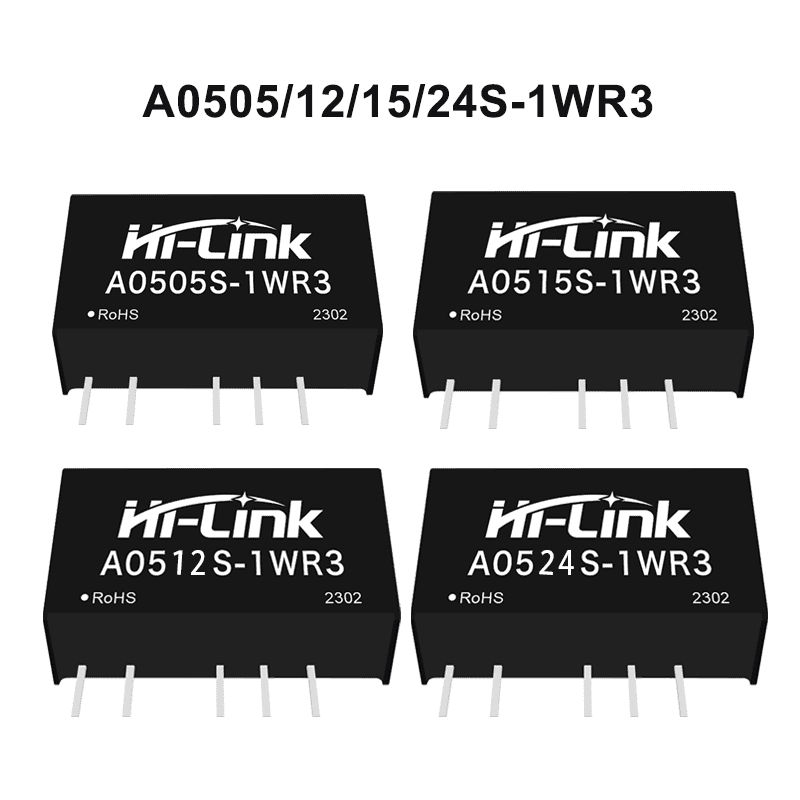
Dual output A0505/12/15/24S-1WR3 5V to 5V/12V/15V/24V 1W DC to DC Isolated constant voltage input non stabilized single output power module
-
Visitor2378
-
Buycount:
-
Price$0.76

Download files:
DC to DC power module:
1W: https://drive.google.com/drive/folders/1vk6luTBKSC5gfwLJC-DbyEZYVDwk87JV
2W: https://drive.google.com/drive/folders/1vjf-77LCVQl16Hcb1phADiU3Hz14mhYB
3W: https://drive.google.com/drive/folders/13pTx02uL4moskJ-PQsBYFytdq2pPt2mN
5W: https://drive.google.com/drive/folders/13pTx02uL4moskJ-PQsBYFytdq2pPt2mN
6W: https://drive.google.com/drive/folders/18IOw7PyIx99lbm3u0FEhkepC82w601sw
10W: https://drive.google.com/drive/folders/1vuJp5ZoJA9Ci0M4wCS8nT689LVzgh2tC
12W: https://drive.google.com/drive/folders/1becUdxQODQ25_A_iarNnun3Vmi_wow1g
20W: https://drive.google.com/drive/folders/182aHyvoN8J0fCurg65jOkfQp17dyaXP6
30W: https://drive.google.com/drive/folders/1StP-0SJDyFpH3yQMLLQjkQXMDXc-RGeP
40W: https://drive.google.com/drive/folders/1IXRm7dueYYTNoyXCFp88wRQexmKAgCLm
B0505S-1WR2: https://drive.google.com/file/d/16BPrOWkzOz7efnf3OvF1XjClKGnO6znv/view
AC to DC power module:
40W: https://drive.google.com/drive/folders/1jI-hITgxjtByhSCpUMmrJATHO8b_gpN7
30W(C): https://drive.google.com/drive/folders/1Nz-_SdQAuVha0JM7nJTelIfophZsmUYb
20W: https://drive.google.com/drive/folders/1PlLOzt_k3Ky5THYGOWP72jqxWSkJsU6Z
15W(C): https://drive.google.com/drive/folders/1vnVfcgQH-OvujpO6asvQvjIgmwUS2Pti
10W: https://drive.google.com/drive/folders/1zaMfq4Dm3brmRWhTGp9-49c8hN5HsIuk
5W: https://drive.google.com/drive/folders/1_dzDfHi9HOnj_b0RJHCGZ9j87ma8PU7g
3W: https://drive.google.com/drive/folders/1xz8MPw9KeQXDlyAQoI3KXzjCoL4yBRVP
2W: https://drive.google.com/file/d/1_UaUPWX9K5Bfavle4C1imVY0-WjY4yso/view
Product Feature
1. Fixed voltage input, isolated and regulated output, power 1W
2. isolation voltage≤1500VDC
3. Low static current and high conversion efficiency
4. Low ripple, low noise
5. output short-circuit protection :Sustainable short circuit protection, automatic recovery
6. operating temperature range :-40°C~+85°C
7. Small SIP package,plastic shell
8. High reliability and long life design,continuous working time MTBF≥3.5 million hours (3500000Hrs)
Enviroment Condition
| Project name | Qualification | Unit | Notes |
| Working enviroment temperature | -40—+85 | ℃ | |
| Storage temperture | -40—+80 ℃ | ℃ | |
| Relative humidity | 5—95 | % | |
| Heat dissipation mode | natural cooling | ||
| Atmospheric pressure | 80—106 Kpa | Kpa | |
| Vibrate | Vibration coefficient 10~500Hz,2G10min./1cycle, 60min.each along X,Y,Z axes | Meet the requirements of secondary road transportation |
Input Characteristics
| Items | Working conditions | Min. | Typ. | Max. | Unit |
Input current (fully loaded/ unloaded) | 3.3VDC Input | -- | 378/6 | --/12 | mA |
| 5VDC Input | -- | 224/5 | --/10 | ||
| 12VDC Input | -- | 93/3 | --/5 | ||
| 15VDC Input | -- | 74/2 | --/4 | ||
| 24VDC Input | -- | 47/1 | --/2 | ||
| Reflected Ripple Current | 4.5 | -- | 15 | -- | mA |
| Impulse voltage (Isec.max) | 3.3VDC Input | -0.7 | -- | 5 | VDC |
| 5VDC Input | -0.7 | -- | 9 | ||
| 12VDC Input | -0.7 | -- | 18 | ||
| 15VDC Input | -0.7 | -- | 21 | ||
| 24VDC Input | -0.7 | -- | 30 | ||
| Input filter type | Capacitive filtering | ||||
| Hot plug | Not available | ||||
Output Characteristics(15v/±34mA)
| Items | Working and test conditions | Min. | Typ. | Max. | Unit | |
| Output load | Load percentage | 10 | -- | 100 | % | |
| Output VoltageAccuracy | Refer to Error Envelope Curve | -- | -- | ±15.0 | % | |
| Linear adjustment rate | Input voltage variation ±1% | 3.3V Output | -- | -- | ±1.5 | % |
| Others | -- | -- | ±1.2 | % | ||
| Load Regulation | 10%~100% Load | 3.3VDC Output | -- | 18 | 12 | % |
| 5VDC Output | -- | 12 | % | |||
| 9VDC Output | -- | 8 | % | |||
| 12VDC Output | -- | 7 | % | |||
| 15VDC Output | -- | 6 | % | |||
| 24VDC Output | -- | 5 | % | |||
| Ripple & Noise | Pure resistive load, 20MHz bandwidth, peak-to-peak | -- | 30 | 80 | mVp-p | |
| Temperature Drift Coefficient | Full load | -- | -- | ±0.03 | %/°C | |
| Output short circuit protection | Continuous short circuit protection, automatic recovery | |||||
| Note: ①The test method of ripple and noise is twisted pair test method. | ||||||
Typical Application Circuits
1. General application:
If it is required to further reduce the input and output ripple, a capacitor filter network can be connected to the input and output
ends, and the application circuit is shown in Figure 1.
However, attention should be paid to the selection of appropriate filter capacitors. If the capacitor is too large, it is likely to
cause startup problems. For each output, under the condition of ensuring safe and reliable operation, the recommended
capacitive load value is shown in Table 1


EMI typical application circuit


Notes:Output Load Requirements
In order to ensure that the module can work efficiently and reliably, the minimum output load cannot be less than 10% of the rated load when in use. If the power you need is really small, please connect a resistor in parallel between the positive and negative poles of the output terminal (the sum of the actual power used by the resistor is greater than or equal to 10% of the rated power and the rated power of the selected resistor must be greater than 5 times the actual power used, otherwise the temperature of the resistor will be higher).
Product appearance size and pin definition, recommended printing layout

or more module mode of this series, please feel free to contact Hi-link team.For more module mode of this series, please feel free to contact Hi-link te

