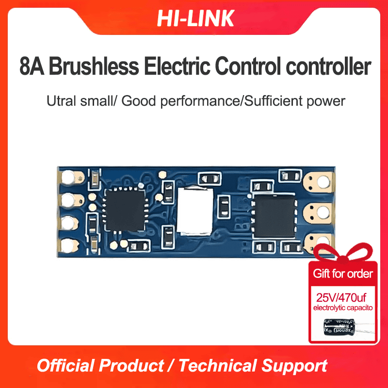
Micro brushless electric control DL03 motor speed regulator module motor drive electric control board input 12V output 8A
-
Visitor7970
-
Buycount:
-
Price$1.00
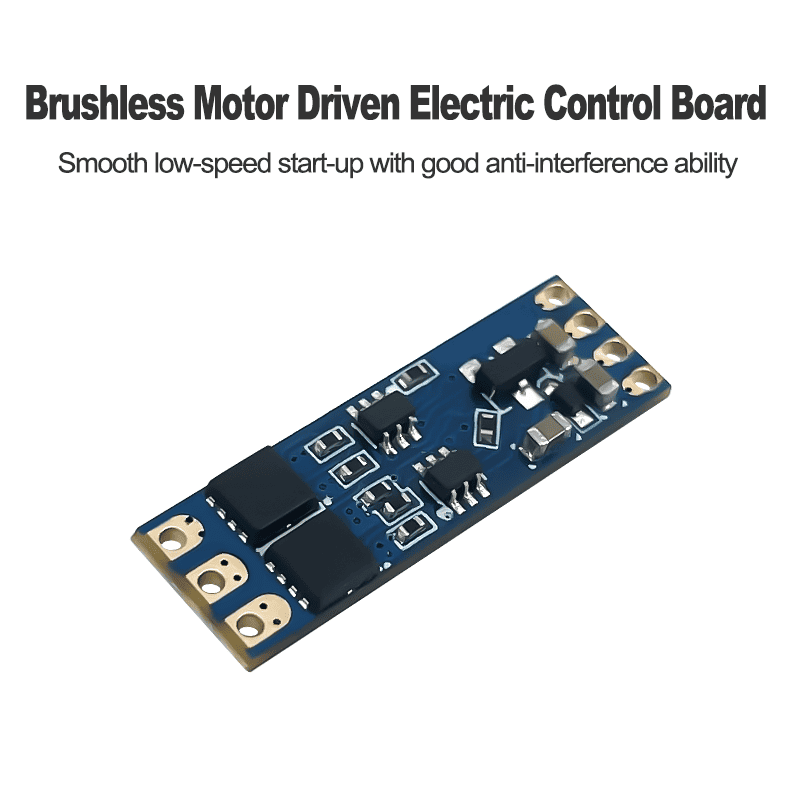
1. Product electrical parameters
Output performance: 8A
Power input: 12V
Control signal type: pwm
Signal pulse width: 0.9ms-2ms
2. ESC module pin definition
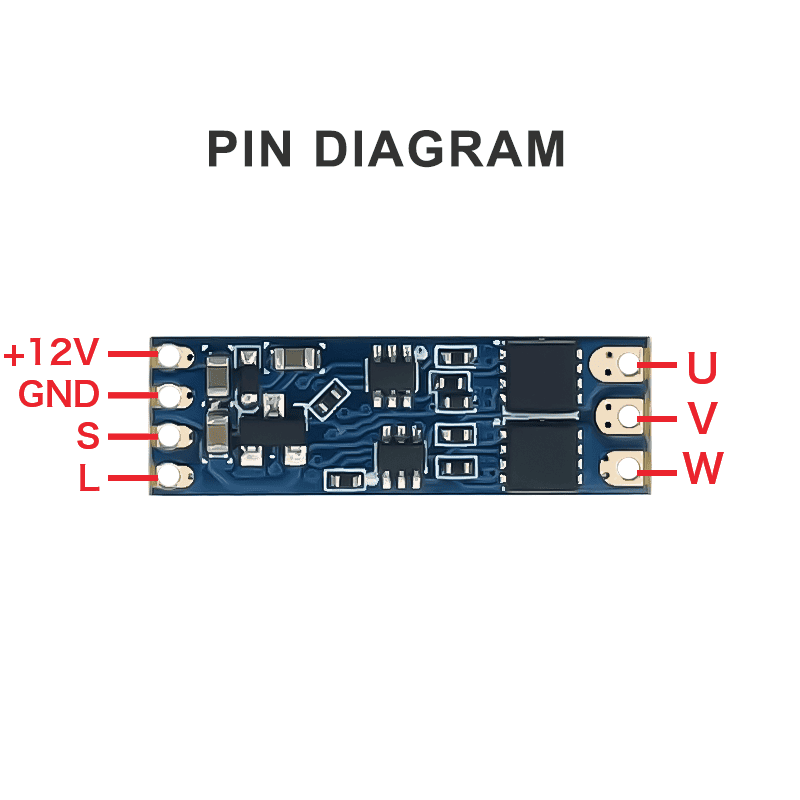
| Pin out | Definition | Pin out | Definition |
| U | Connect the three | Positive electrode | Power input 12V |
| V | wires of the brushless motor | negative electrode | Power Ground |
| W | S | Signal line (PWM signal) | |
| L | Indicator light (the light turns on when the cathode is connected) |
3. ESC stop control

When a 50Hz PWM signal with a pulse width of 0.9ms is input to the electric control signal line, the motor stops rotating.
4. ESC start control
To start the motor, you need to give the ESC a stop signal first, and then after a delay of 2 seconds, give the ESC a signal greater than 0.9ms, and the ESC will start the motor. If you directly give the ESC a signal greater than 0.9ms, the motor cannot be started.
5. Motor max speed control

When a 2ms pulse width, 50hz PWM signal is input to the ESC signal line, the motor will run at maximum speed.
6. ESC controller
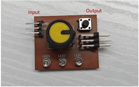
Introduction to the ESC controller: As shown in the figure above, it is divided into input and output terminals. The pin definitions are shown in the following table. The signal pins at the input terminal are temporarily inactive. The right side can be connected to three sets of servos for testing. The knob controls the output of the PWM signal, and the button is used for mode selection.
| Input pin definition | Output pin definition |
| GND | GND |
| 5V | 5V |
| S(single line) | S(single line) |
After the ESC controller is connected to the power supply, the three lights are on at the same time, and then only LED1 is on. Different LED lights correspond to different modes,and the corresponding situations are shown in the following table:
| Lamp | Model | Explain |
| LED1 is on | Manual mode | In this mode the rotation of the motor is controlled by adjusting the knob. |
| LED2 is on | Median Mode | Centering test. |
| LED3 is on | Automatic mode | The servo will rotate continuously,and then rotate in the opposite direction after it gets stuck. |
7. Brushless motor
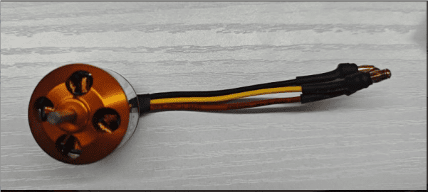
| Pin out | u | v | w | |
| Corresponding color | red | black | yellow |
7. Using wiring tutorial

Steps:
(1) Adjust the knob of the ESC controller to the minimum and connect the 5V power supply of the ESC controller .
(2) Connect the 12V power supply to the ESC . You can hear the ESC start-up sound.
After about 2 seconds, a long "beep" sound is emitted, indicating that the self-test is normal . It means that everything is ready and you are waiting to push the throttle to start the motor.
If there is no response, please check whether the 12V power supply is intact and whether the 12V power supply connection is reliable.
If the motor emits a "beep-beep" sound 2 seconds after power-on, it means that the servo knob is not adjusted to the minimum and the throttle channel is reversed. Adjust the knob to the minimum until you hear a long "beep-----" sound .
If the motor makes a "beep-beep, beep-beep, beep-beep" sound (at intervals of 1 second) after power-on, it means that the power supply voltage is too low or too high.Please check the power supply voltage.
(3) Adjust the mode of the ESC to manual mode, start turning the knob , and the motor will start to rotate.
Note: When the operating current exceeds 2A, please ensure proper heat dissipation of the ESC, otherwise the ESC module will be burned out.

